

The output transformer is one of the central components in an amplifier – going by mass alone, unquestionably the main one. Tomasz Lachowski of Toroidy helps us understand what exactly it does, how it does it, and whether there are alternatives to the ubiquitous EI transformer.
An amplifier’s ability to drive a loudspeaker load depends primarily on its damping factor – that is, the ratio of its output impedance to the input impedance of the loudspeaker. The lower the amplifier’s output impedance, the more rigidly it can force its voltage into the speaker, and the less variations in the speaker’s impedance curve will affect the frequency response. When we now realize that a typical loudspeaker has an input impedance between 4 and 8 ohms, while a vacuum tube can easily have an output impedance of around 1.5 kilohms, it quickly becomes clear that tubes aren’t inherently well suited for power amplification.
This is where the output transformer comes into play. In a circuit, it serves a function similar to that of a gearbox, transferring electrical power from the input-side coil – the primary winding – to the output-side secondary winding by means of electromagnetic induction, while converting (transforming) voltage and current. If the primary has fewer turns than the secondary, the output voltage increases in proportion to the turns ratio (it is stepped up), while the current decreases by the same ratio. The output power therefore always corresponds to the input power – minus transmission losses, which are relatively small in well-designed transformers and which we will ignore here for the sake of simplicity.
The example above describes a step-up transformer; for our tube amplifier, however, we need to work in the opposite direction and therefore require a step-down transformer whose primary has many times more turns than the secondary. This lowers the voltage while increasing the current accordingly. Since the power remains the same on the one hand, and impedance according to Ohm’s law is calculated as voltage divided by current on the other, stepping down the voltage effectively reduces the output impedance – and voilà, that’s exactly what we needed.
EI Output Transformers
For this to work well, however, the transformer must be well designed, as hinted earlier. “Well designed” means, first of all, that the magnetic field induced by the primary coil – which in turn induces the voltage in the secondary coil – is utilized as completely as possible. By winding the coils around an iron core that has a magnetic permeability many times higher than that of air, the magnetic field can be effectively concentrated and guided into the secondary coil. In addition, the primary and secondary windings are not wound side by side, but interleaved with one another. This overlapping allows for good magnetic coupling and effectively forces the magnetic field to pass evenly through both windings, minimizing leakage losses.
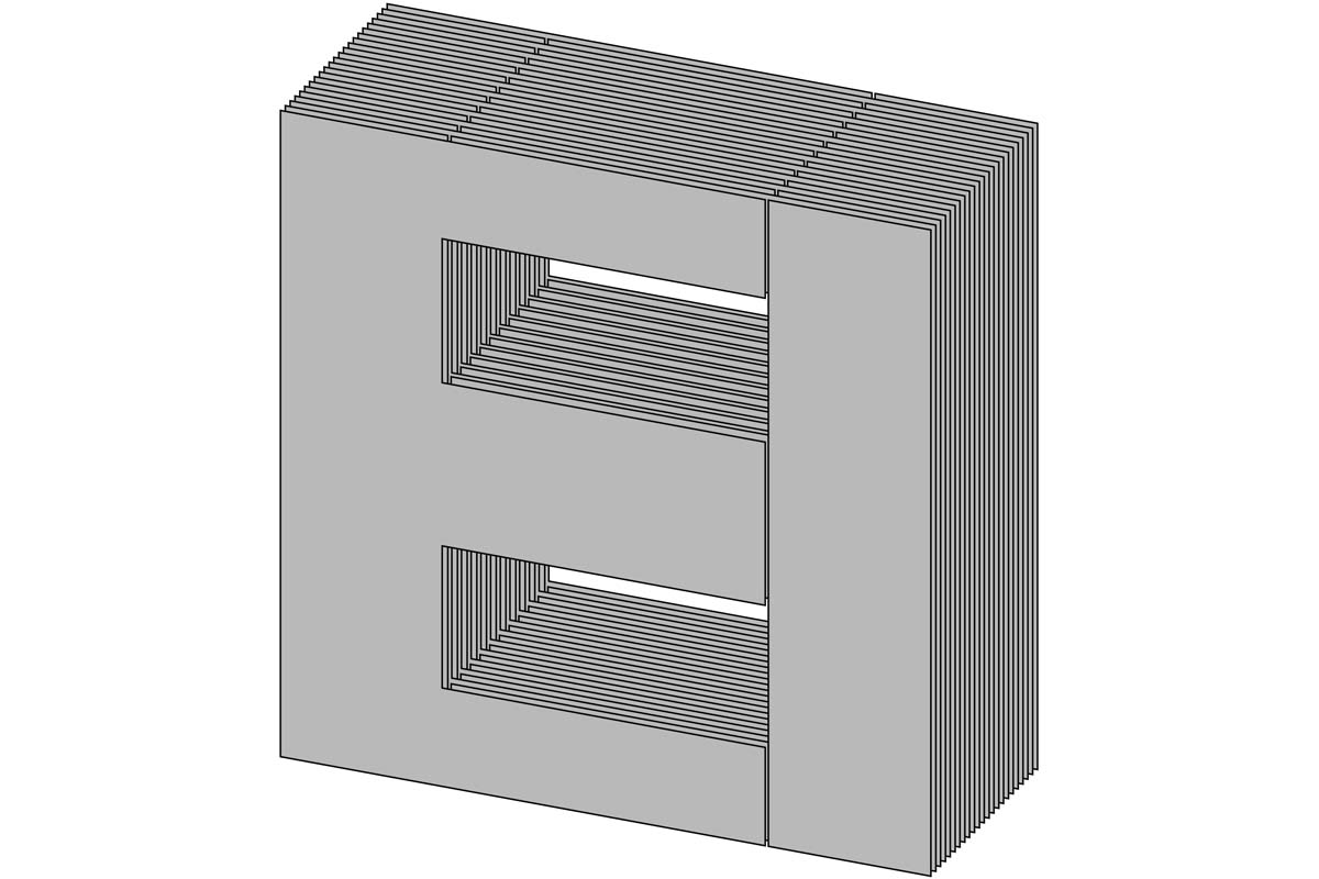
To give the magnetic field an easier return path, an unwound leg can be added on each side of the wound iron core, and the three legs can be connected at the top and bottom by crossbars. The result is an iron core shaped like a “square figure eight.” Since this core usually consists of an E-shaped element, onto whose center leg the windings are slipped, and which is then closed into an “eight” by adding an I-shaped bar, this most common form used in output transformers is known as an “EI core.”
Compared to air-core coils, a transformer with an iron core is far more efficient and can also be made more compact. However, the core also stands in its own light in a way: the magnetic field flowing through it uses part of its energy to induce eddy currents, which reduce the transformer’s efficiency through heat generation. To solve this problem, designers take advantage of the fact that eddy-current losses scale with the square of the core thickness: halving the thickness therefore reduces the losses to one quarter. By building the core from hundreds of extremely thin, electrically insulated laminations – within which only microscopically small eddy currents can form – the losses can be reduced to a fraction of what would occur in a solid core.
Constrained At Both Ends
This largely eliminates the efficiency problem, but another remains: bandwidth. A transformer acts like a low-pass filter whose lower cutoff frequency depends on the inductance of the primary winding – the higher the inductance, the lower the frequencies that can be transmitted. High inductance is achieved mainly through a high number of turns. The downside, however, is that many turns create capacitance within and also between the windings, which in turn produce a low-pass effect and thus limit the bandwidth at the high end.
By using a larger core, it is possible to achieve greater inductance with the same number of turns and thus reach the desired lower cutoff frequency without the transfer curve already rolling off within the audible range. However – as most tube enthusiasts are painfully aware – a very large and heavy transformer is usually required to cover the entire audible spectrum.
Single-Ended Loading
In single-ended amplifiers, the problem is exacerbated further by the phenomenon of magnetic saturation. Induction occurs through a change in magnetic flux in the core, which is not an issue in push-pull amplifiers because music is an AC signal. Magnetization therefore alternates in both flux directions, and the core oscillates around an unmagnetized state. This, of course, requires proper biasing: the positive and negative amplification elements should ideally have no offset between their quiescent currents, so that their sum is zero and the core is not magnetized at idle.
In single-ended amplifiers, one amplification element handles both half-waves. This is only possible if it is held at a relatively high DC current at idle (the quiescent current), which leaves room on the transfer characteristic for both the positive and negative half-wave of the music signal.
This bias current magnetizes the transformer core continuously in one direction. If the core has high magnetic permeability, it is driven close to saturation – meaning it has little remaining capacity for further increases in magnetic flux. If, in this state, it is required to transmit a music signal swinging in both directions, it lacks headroom on the positive side and can no longer reproduce the positive half-wave correctly. The result is distortion, especially in the bass range, where amplitudes are particularly large.
The solution here, as so often, is a compromise: a defined air gap is maintained between the “E” and “I” elements of the core. This reduces the permeability of the core and ensures that it can tolerate a certain amount of DC current without approaching saturation. Since permeability is crucial for inductance, however, this DC tolerance is paid for with reduced efficiency and a narrower bandwidth – the core then requires even more turns or an even larger size.
The Toroidy Approach: Slicing the Donut
Because toroidal transformers require far fewer turns to achieve the same inductance – thanks to windings that completely enclose the core – they promise the possibility of making the output transformer significantly more compact and lighter. Above all, their greatly reduced stray capacitances allow for a much wider bandwidth. Especially in single-ended amps, however, they run into a design problem: since their core is not assembled from two parts but instead rolled into a continuous ring from a single strip of steel – much like the mainspring of a clock – the required air gap is considered difficult or even impossible to implement. Essentially, all common methods of cutting into the core would create short circuits between the lamination layers.
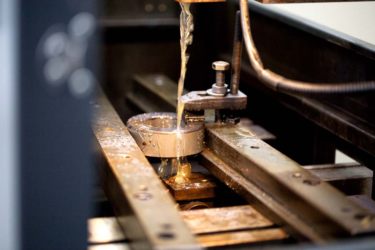
Toroidy has developed a process that allows a microscopically fine air gap to be cut into the transformer core without damaging the insulation between the individual lamination layers. The result is a transformer that, due to its higher permeability, requires significantly more effort in the development of the amplifier topology to avoid saturation, but in return can offer a bandwidth of around 8 Hz up to 150 kHz and beyond.
Special thanks to Tomasz Lachowski of Toroidy.